How to Wire an Irrigation Controller
Aug 22nd 2024
Irrigation systems significantly rely on the controller, which controls valves and regulates water flow. Having control over your irrigation system is essential for any gardener. The irrigation controller is the brain of your irrigation system. It signals valves to open and close at a specific time and duration. A wire connects the controller to the valve.
Controllers can either be AC or DC. It is important to remember that AC controllers are incompatible with DC valves and vice versa. This means you will need DC valves for the DC controller. If you're wondering how to wire a valve to the controller, keep reading to learn the process. Here is a step-by-step guide on how to wire an irrigation valve to an irrigation controller and automate your irrigation system.
Wiring an Irrigation Valve to Irrigation Controller
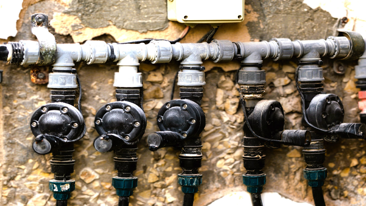
After installing the manifold, you can wire each valve to the controller. The wires must reach the area where you want to install the controller.
Tools and Supplies Needed
For wiring a controller, you will need the following supplies:
- Wire strippers
- A wire consisting of multiple-colored wires. White wire is known as common wire. Professionals usually use white for common wire, but the color is not important as long as the color of the common wire is consistent. The most common wire sizes for a sprinkler system are 16-gauge and 18-gauge.
- Waterproof wire connectors: Wire connectors protect the wires from potential water damage or corrosion, which can cause various electrical issues or valve failures.
Unplug the Timer and Turn the Power Off
Unplug the controller to protect yourself from electrical shock. Turn off the power and water supply to the sprinkler system for extra protection.
Connect Valve Solenoids to Color-Coded Wires
Each irrigation valve has a solenoid, which uses electricity to determine the water pressure passing through the valve. The solenoid will have the same-colored wires if it's DC and different-colored wires for AC valves. You will probably see multiple solenoids if you have multiple irrigation zones around the yard.
The color-coded wires are called hot wires or station wires. One wire on the solenoid will be connected to one of the color-coded wires that connects to the controller. Remove the outer sheathing of the wire using a wire stripper, then twist the metallic parts of color-coded wire and solenoid wire together. Note down which color of wire is designated for each zone. You must remember this when connecting the wires to the controller.
Connect Valve Solenoids to Common Wire
Now you have connected one wire from each solenoid to one separate color-coded wire; you will be left with a second unused solenoid wire. Use wire strippers to remove the cover of the solenoid wire and common white wire that will connect to the controller and reveal the metallic wires. Twist the black wires of all solenoids to the white common wire.
Cover Wire Connections with Waterproof Caps
Cover each wire connection with a waterproof connector. You should have a wire nut connector over each connection of color-coded wire with one of two solenoid wires and a wire nut over the pairing of white common wire with other solenoid wires. Twist the connector tightly over the wires to protect connections from moisture. If the wire connector spins without tightening, it means the metallic tip of the wire is extra-long. Cut it shorter until the wire connector fits tightly around it.
Pass Wires Through the Controller
Open the bottom of the controller by removing the bottom panel to feed the wiring. On one cable end, you will now have wires connected to valve solenoids and covered with wire nut connectors. On the other end, you will have the other end of color-coded wires and common wires. Thread the cable up through the bottom hole in the controller.
Connect Wires to Stations or Zones
Thread each color-coded wire to its designated zone. Review the notes you took to ensure you connect the right colored wire to the right zone. Otherwise, you will program the timer incorrectly. Push the wires one by one into the marked zones inside of the box and hand-tighten them with a screwdriver to secure the wires. Then, push the white wire into the common wire slot on the controller and tighten it using a screwdriver.
Test the Connection
- Before restoring the power and water: Double-check that all wire connections are capped and secured safely.
- Turn on your controller to ensure everything is working in order.
- Turn the controller dial to Station 1 and press Start. If the wiring is connected correctly, the solenoid will begin to make noise.
Additional Information on Wiring the Controller
Use a waterproof wire connector for each connection. The common wire will connect to one lead from each solenoid. A different colored wire will be connected from the controller to each remaining leads on each valve solenoid.
Final Takeaway
There you have it—a complete process for wiring the valve to the irrigation controller. A controller or timer is one of the main components of an irrigation system. The controller isn't just a timer; it has multiple features to help save money on water bills and maintain an efficient watering schedule. It regulates and controls the system by directing it when and for how long each watering zone should run. An irrigation system with a controller will save you time and water. You can use 16 AWG or 18 AWG wires to wire the controller.
Are you looking for a high-quality controller or timer for your irrigation system? DripWorks carries a variety of AC, DC, solar, and wind-up timers. Explore our timer collection and find the one that best suits your system layout. DripWorks offers everything you need to get your irrigation controller installed and ready for your irrigation system.

